light-controller-progress
🧪 Why I Started This Project
I’ve had my WiFi-controlled Tapo lights for a couple of years, and I enjoy the ability to get the vibe in my room just right. For instance, as I’m winding down for bed, I can set them to a dim, warm orange, and when I wake up, I can make them turn on automatically at full brightness in a daylight colour. The main issue I’ve found with it is that I currently have two forms of control: either through the Tapo app on my phone or by speaking commands to my Google Home Mini. As I’ve experienced in several instances, neither of these options are optimal for me. For example, if my phone is in another room, or it’s late at night, and I don’t want to yell across the room to turn off my lights. Of course, this problem has been solved for non-WiFi-controlled lights with a simple wall switch.
My goal was to create a simple-to-use physical remote for my WiFi lights. My requirements were:
- Portable: I wanted the remote to be able to sit by my desk and, when I went to bed, be on my bedside table. So, being battery-powered is essential for me
- Low-power: This requirement aligns with the above, as I would prefer a battery-powered remote that doesn’t run out of battery quickly. Will have to look into features like deep sleep and generally lower-powered components
- Immediate feedback: I wanted any adjustments made using the physical components I use to be immediately clear about what they do. I’m aware that changing my lights by contacting an API introduces some latency in the adjustments made. This means I’ll want an additional status indicator that displays what my lights are currently showing and responds immediately to button or dial presses.
- Feature complete: I wanted to be able to control my lights in every way I’d typically do with my Google Home or phone. So that means not just on/off, but also brightness and colour.
⚙️ Current Hardware Setup
I’m currently running everything on a breadboard. The setup includes:
- ESP32 – runs the control logic, connects to
WiFi, and interfaces with the Tapo API
- Rotary encoder – rotates to dim/brighten the
lights, push toggles on/off
- Arduino joystick module – rotates to adjust
hue, push resets to warm white
- PIR motion sensor – detects whether someone
is using the controller and triggers deep sleep when idle
- 24-bulb RGB LED ring light – shows real-time visual feedback (brightness, colour, etc.)
🧠 Logic + Behaviour
Currently, to meet my low-power requirement, the ESP32 starts in deep sleep with the LED ring light off. When the PIR motion sensor detects movement in the room, it wakes the ESP32 from deep sleep and initiates its boot-up process. This involves connecting to the WiFi, establishing a connection with the Tapo lights, and turning on the LED ring light. The ring light shows the current status of the Tapo lights. Currently, I am storing the previous state of the lights (colour, power, and brightness) on the ESP32’s disk so that when it wakes up, it can retrieve the last state of the lights and display it on the ring LED.
The ring light aims to display both the current colour, brightness, and power state of Tapo lights. I map the ring’s RGB LEDs to the hue range (0–360°) so it mirrors the Tapo lights. For power, it is on when the lights are on and off otherwise. For brightness, as there are 24 bulbs in the LED ring, I’m making each bulb display ≈ 4% of the brightness. For example, if the brightness of the Tapo lights were 50%, 12 out of 24 bulbs on the ring light would be on.
The rotary encoder deals with the brightness and power state of
the lights. The library I’m using is
AiEsp32RotaryEncoder, which supplies the method
setBoundaries (minVal,maxVal). I set the min/max
values to be 0-24, so then rotating the encoder directly
corresponds to the ring LED. I converted that into what the Tapo
lights brightness should be with: $$\text{brightness}=(int)\ encVal*\left(
\frac{100}{24} \right)$$
For the joystick, the inputs it provides to the GPIO ports of the ESP32 are axis X and axis Y, as well as CLK (when the joystick is pressed). Using some basic trigonometry, I’m converting the x and y components into the angle around a circle (0-360 degrees):
$$angle=\frac{\arctan {\frac{y}{x}}*180}{\pi}$$
To set the Tapo colour and brightness level, I modified an existing open-source Tapo API client for the ESP32. Their version only included API calls to turn on/off the lights, so I forked their repo and manually added the methods:
set_brightness(uint8_t level)set_colour(uint16_t hue, uint_t saturation)
📉 Dealing with Latency
To align with my immediate feedback requirement, I wanted to ensure it didn’t feel ‘laggy’ or cumbersome to use. My initial testing felt disappointing, as I’d rotate the encoder, then have to wait one or two seconds for the Tapo lights and ring LED to adjust. This created a user experience of turning it slightly, then waiting for the lights to update, turning it a bit more, and waiting again, etc. I’d have to address issues with two different components: the Tapo lights and the ring LED light.
For the ring LED light, the solution was relatively obvious. In my Arduino code, I moved the ‘update_ring_light’ method before the blocking API call to the lights was made. This ‘update_ring_light’ method is responsible for updating the ring light’s display based on the current state of the Tapo lights. By moving it before the blocking API call, the ring light responded immediately to the user’s control, fulfilling that immediate feedback I wanted.
For reference, I change my code from this:
long encVal = encoder.readEncoder();
if (encVal != prevEncVal) {
    prevEncVal = encVal;
    brightness = static_cast<uint8_t>(encVal);
    if (!allOn) toggleAll();            // turn on if currently off
    setAllBrightness(brightness); // changes tapo lights
    update_ring_light(brightness);
}
To this (with the local ring light call before any network requests):
long encVal = encoder.readEncoder();
if (encVal != prevEncVal) {
    prevEncVal = encVal;
    brightness = static_cast<uint8_t>(encVal);
    update_ring_light(brightness); // immediately update ring light
    if (!allOn) toggleAll();            // turn on if currently off
    setAllBrightness(brightness); // changes tapo lights
}
For the Tapo lights, improving the latency and performance wasn’t as obvious. Due to the requirement to make an API call to control the lights, there was a definite lower limit to how quickly I could get it to respond. One solution I came up with was to parallelise the API calls so both of my Tapo lights would adjust to their updated state simultaneously rather than sequentially. As I have two Tapo lights, this effectively cut the waiting time for the lights to update in half completely. Another improvement I made was to change the API calls from blocking to asynchronous. I achieved this by creating two threads: one for my core application logic (connecting to WiFi, reading encoder values, etc.) and the other solely for Tapo API calls. The two threads communicate through a shared mutex, which contains the current brightness, power, and colour state that the lights are expected to be in. The Tapo thread regularly checks these mutexes, and if they are out of sync with how the lights are currently set, it’ll call to update them. Separating the logic in this way came with several benefits. Previously, every adjustment to the joystick or rotary encoder made a blocking API call to update the lights. Now, even if the user changes many values rapidly, this will only update the value of the mutex, meaning the API calls now occur at regular intervals. In practice, this allows me to adjust the control as much or as quickly as I like and for the Tapo lights to update to whatever I finally settle on.
🎯 What’s Next
In terms of what’s next, I’d like to avoid having a bundle of cables on a breadboard for very long. My next step would be to make a more semi-permanent prototype using a solder-able prototyping board. This will allow the circuit to be less fragile when moved and enable me to start considering casing options.
For the exterior of my remote, I’m planning to 3D print a minimal case to hold all the components in the correct positions. For example, I need to position the joystick and rotary encoder next to each other for control and have the PIR motion sensor mounted in a way that, when placed in different locations, it’ll always be able to detect motion correctly. Once I have this 3D shell, I’ll explore other materials I could use for the cover of all the components. I don’t particularly want to use 3D printing for the visible exterior case, as it’ll look and feel cheap and poorly made, which will detract from my experience of using it and my enjoyment of using this over my phone or Google Home. For the exterior shell, I’m considering using wood or plaster. These would give the remote a more polished feel, which plastic wouldn’t. However, with great polish comes great difficulty, as working with wood or plaster would be significantly more complex. I’m aiming to address these changes further down the line once I have the interior, minimal 3D-printed shell.
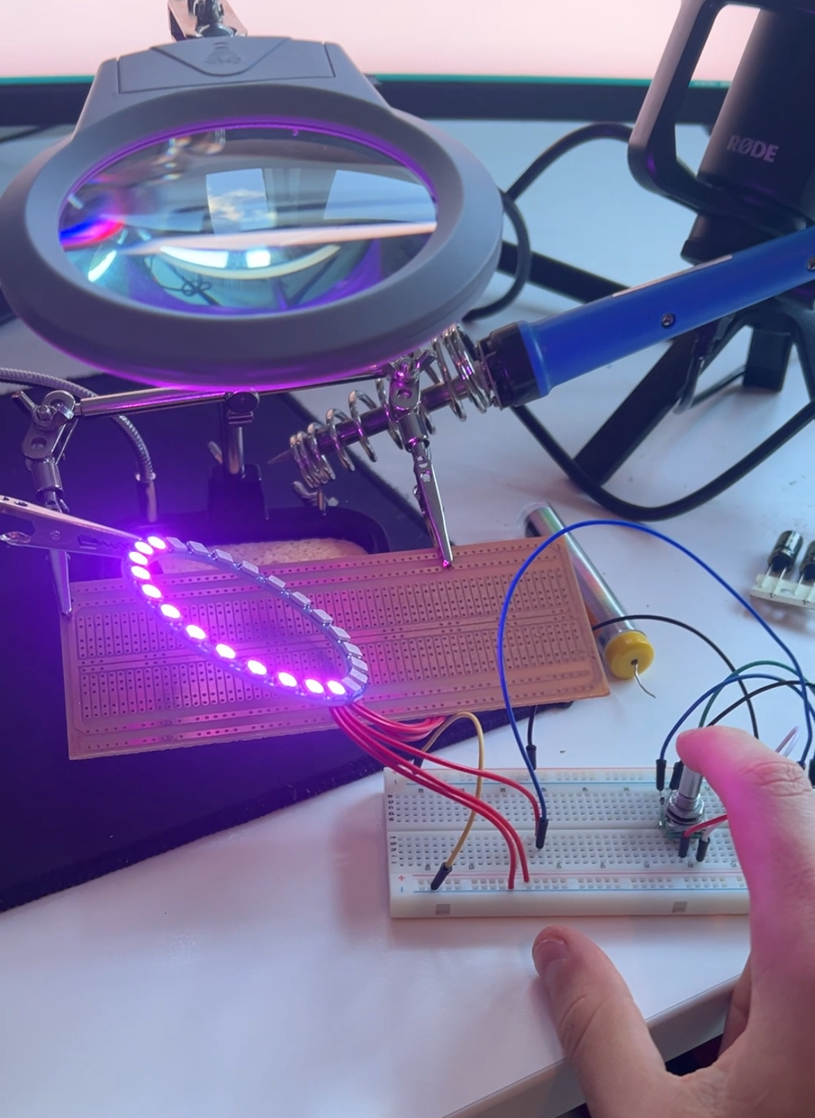
📸 Photos
Heres a pic of my rotary controller setup on my breadboard with the LED ring light.